Magneto Timing Synchronizer
Despite its simplicity, the magneto timing synchronizer, commonly referred to as the magneto timing tool, can be one of the most frustrating tools for even the most experienced mechanic to use. The difficulty of using this tool can be baffling as the theory of operation is as simple as it gets. Connect a lead to the magneto ground point, connect a lead to the p-lead terminal, and as the magneto rotor shaft is turned, a light on the front of the tool will turn on and off as the contact points open and close.
All too frequently, however, a mechanic will struggle with timing a magneto, unable to get the tool to indicate that the contact points of one or both of the magnetos are opening. The typical action is to send the magneto back to us for warranty inspection, only to be informed that the magneto contact points operated perfectly normally when checked on the bench.
This discussion will take a closer look at how the magneto timing light tool can contribute to false diagnosis of a magneto problem.
The Tool
For the purposes of this topic, the Magneto Timing Synchronizer will be referred to as a Magneto Timing Tool. Of course, this tool has other names, ranging Buzz Box as a nod to the buzzing or whistling sound that backs up the on and off illumination of the timing lights, to other, very salty terms when struggling with the tool on a late Friday afternoon.
From the theory of operation standpoint, the magneto timing tool is not a continuity tester, at least in the conventional sense of how a continuity tester works. The principle of operation for a continuity tester is to introduce a voltage signal to a circuit. If the circuit is open, there will be no continuity and if the circuit is closed or complete, then there is continuity. If used on a magneto, the circuit is open when the contact points are closed, and the circuit is open when the contact points are open.

However, the slight introduction of a voltage is a theoretical safety issue as the voltage from a battery-operated continuity light or a multimeter can charge the electrical circuit and potentially enable it to discharge a spark. So, at some point in the past, a method to passively detect changes to the magnetic circuit of the magneto, or inductance of the magneto electrical circuit, was established to be the correct method. As such, all proper magneto timing tools are based on measuring induction, not continuity.
Inductive magneto timing tools are available in two different styles: mechanical contactor type or solid-state type. Both tools work to the same method of using lights and sound to signal contact point opening and closing, changing the indicating lights and sound based on changes to the magnetic density of the electrical circuit of the magneto.
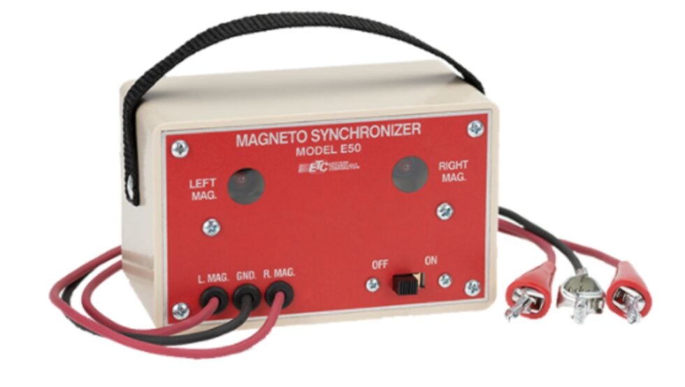
The gold standard of the mechanical contactor type of magneto timing tool has been the Eastern Electronics E50. Hundreds of thousands of these tools have been produced, and it is virtually impossible to not find this tool in a well-equipped shop. The theory of operation is that the contactors are energized by the internal battery, and when connected to the magneto to detect the contact points are open, the indicator lights will turn ON, and the tone of the tool buzzer changes. The Eastern E50 does not have any instructions on the tool to indicate whether the indicator lights should be on or off when the points open, so the mechanic using the tool must confirm how the lights and buzzer actuate by grounding connecting the contact lead to ground to observe how the tool operates.
The solid-state magneto timing tool works in a similar way, except with no mechanical parts. The sensing of the magneto flux is accomplished strictly by electronics, no mechanical contactors are used. A big difference, though, is the lights turn OFF when the contact points open. The obvious initial concern is that the mechanic using either tool MUST know how it works. The solid-state units have instructions printed on the front that the lights will turn off, or be out when the contact points open.

The timing tool requires specific connections
Countless magnetos are incorrectly determined to be faulty due to the failure of the installer to connect the tool to the magneto correctly. Follow these simple connection rules and the magneto tool will work as required to time the magneto.
Slick magnetos: Connect the tool and use the fiber washer to prevent the tool lead from grounding and causing a false indication on the timing tool that the contact points are grounded and not opening.

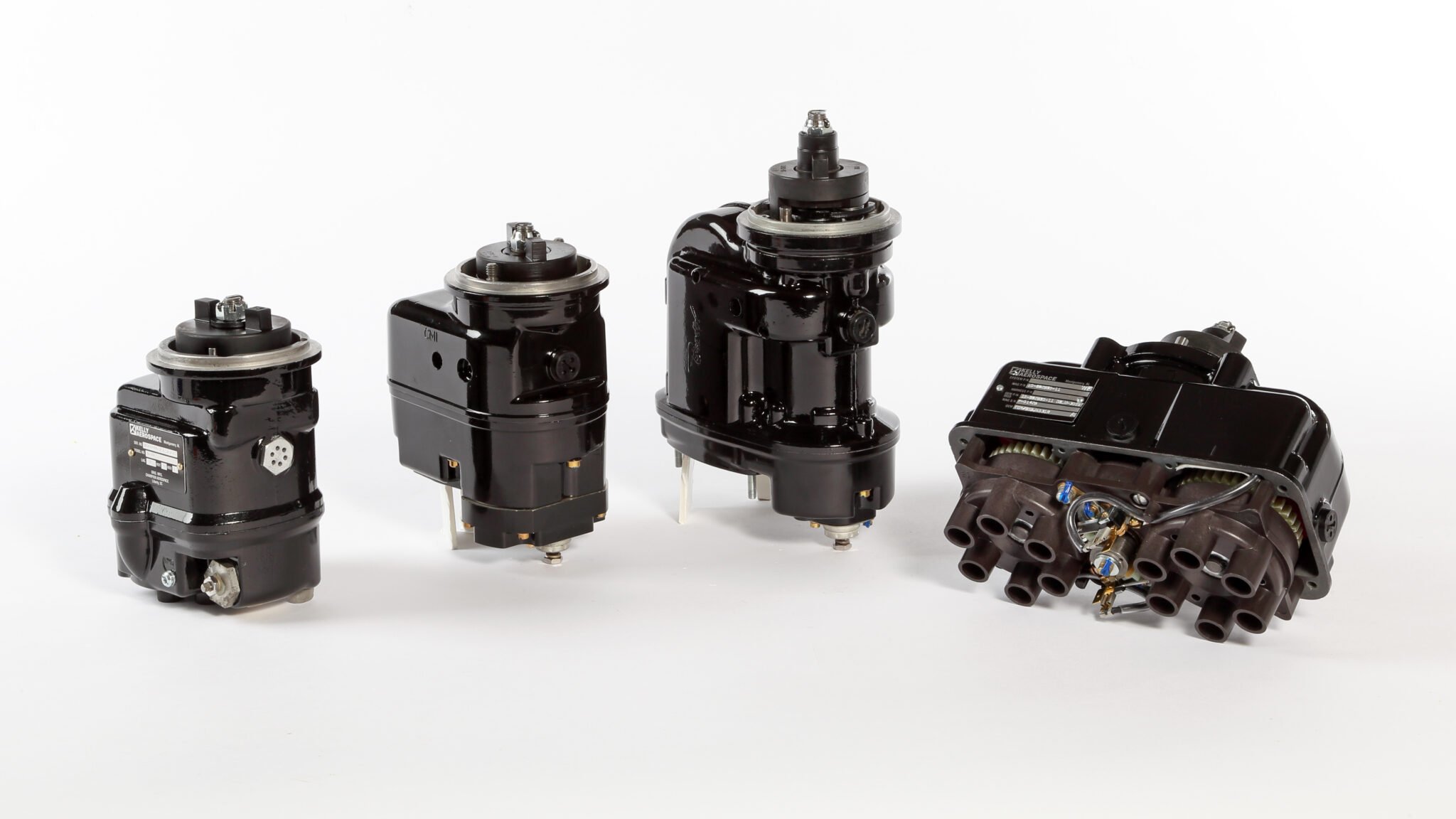
Bendix Magnetos
The short cover magnetos that use a simple capacitor stud for the P-lead connection require the same fiber washer to ensure that the timing tool lead does not ground and send the wrong signal.

Inspect the magneto with the timing tool BEFORE installation
Step One: Confirm that the tool works before removing and installing magnetos. Low battery voltage, especially with the solid-state tool, can still illuminate the lights, but is likely to not be sufficient to provide enough voltage to sense the change of the magnetic circuit in the magneto. If the tool has not been used for several months, it is a sure bet that the batteries are weak and need to be replaced for accurate operation.
Step Two: Check the magneto for operation BEFORE installing on the engine!! With the magneto on the bench, connect the timing light and confirm that the timing lights illuminate correctly to show contact point opening or closing. In addition, the internal timing of the magneto can very easily be confirmed before installing on the engine.
- Insert the timing pin into the distributor gear in the hole that corresponds to magneto ROTATION, not the position on the engine. For example, the right position magneto on a Continental O-200 is LEFT rotation, so the timing pin is inserted into the L hole.

- With the pin inserted, the rotor shaft can be moved very slightly. The timing light should turn on and off as the contact points open and close. If the pin has to be removed and the rotor shaft turned 90 degrees so the contact points open and close, then the internal timing is possibly incorrect. The magneto should not be installed until the internal timing is confirmed or corrected.

- If the magneto passes the bench test, then it is ready to install.
Bendix Magnetos- 20/200/1200/Dual Magneto Series
- Remove the vent plugs on the magneto to expose the red painted gear tooth.
- Turn the rotor shaft so that the red painted gear tooth moves within the range of the vent plug hole. The timing light should turn on and off as the contact points open and close. If the rotor shaft is turned 90 degrees so the contact points open and close, and the red gear tooth is not visible in the vent plug hole, then the internal timing is possibly incorrect. The magneto should not be installed until the internal timing is confirmed or corrected.

- If the magneto passes the bench test, then it is ready to install.
Final magneto installation and timing
Making a solid ground lead connection between the magnetos and the timing tool is critical. This is the single most often missed step when using timing light tools, and will invariably result in a false diagnosis of magneto timing or incorrect magneto to engine timing.
The magneto timing tool uses a very low voltage to power to power the tool to sense the changes to the magneto magnetic circuit. The ground path from the tool to the magneto has to be direct between the magneto and tool, and as short as possible. If the timing tool ground lead is connected to the engine, it is almost impossible for the tool circuit to complete the necessary ground path through the magneto to properly illuminate lights when the contact points open and close.
The best method to ensure a continuous ground path between BOTH magnetos and the timing tool is to connect an extra jumper lead. Connect the timing tool ground lead to the ground point on the primary magneto. Next, connect a jumper lead to run from the common connection of the timing tool ground on the primary magneto, to the ground point near the secondary magneto contact points. This extra lead provides for a solid ground path and will eliminate the majority of timing problems in which the contact points seem to not open or close as expected.

DO NOT CONNECT THE TIMING TOOL GROUND LEAD TO THE ENGINE OR AIRFRAME! The path to ground may not be connected if there is too much distance between the timing tool ground and the magneto ground.

That’s it for timing tool discussion, give the techniques discussed a try. If you have time, experiment with the tool to see where things can go wrong due to a mistake with a simple connection. As always, feel free to suggest a magneto topic for future discussions.
Related Posts
Hartzell Engine Tech, a trusted name in aviation, proudly announces the launch and immediate availability…
Read More
Inspecting your aircraft’s exhaust parts is crucial. One small exhaust discrepancy can result in carbon…
Read More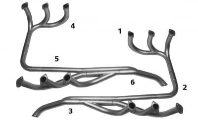
When optimizing or repairing your aircraft’s exhaust system, many details must fall into place for…
Read More